
Friday, October 21, 2011
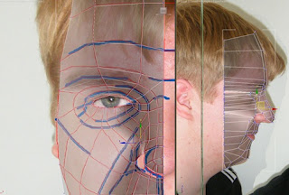
Eye
For the eyes a sphere was created to be placed inside the model. Once the sphere was in the correct place however, it showed that the eyelid was not the correct shape. The eye lids were then pulled forward until they were positioned just overlapping the sphere. A symmetry tool was then used on the eye to create a second. The mirror was moved to the exact same position as the face mirror so that the second eye ball would be in the same position on the other side of the face. An eyelid material was then applied to the eyeball and adjusted slightly so the image was not stretched and the pupil was facing in the correct direction.

Ear
To create the ear first topology lines were drawn in Photoshop. Using the same method used on the face, the ear was split into four sided polygons. The new reference plate was again loaded into 3ds max with the new ear topology.


In the left viewport, the line and snap tool was used to draw over the topology lines of the reference plane. One of the lines was selected and was converted to an editable poly. All the other polygons were then attached to the editable poly and the vertices were weld together. Using the front reference plane, the vertices in the ear were pulled in the correct position in the Z axis.

The ear was then attached to the rest of the head and moved into position ready to be weld in position. However there were not enough polygons on the side of the face to attach the ear properly.

The problem was how to attach the ear without using any triangles or polygons with five sides. The amount of vertices on the face to connect to the ear was only four however on the ear there was eight vertices. First the ear vertices were decreased to four, using a four sided polygon in-between every pair of polygons on the ear.

The new vertices were then snapped to the face vertices and weld together.

Once the front of the ear was connected, the back of the ear needed to be created. This was done by selecting the edged of the ear and holding shift while moving the edge in the Z axis. This created a copy of the edges giving the ear depth. The edge was copied again only this time the scale was decreased to create behind the ear. The next stage was to weld the back of the ear to the rest of the face. Using the same method used for the front of the ear, the back of the ear was connected and weld to the face.


Thursday, October 20, 2011
Back of Head and Neck
After the front of the head was completed, the next stage was to complete the rest of the head, making sure the polygons continue to flow in the same direction and all have four sides. The reference plane was edited in Photoshop to add more tropology lines to identify the flow of the back of the head. In 3d studio max the new reference plane was loaded into the plates. A sphere was created and resized to match the size of the head. The sphere was used as a shortcut to create the top of the skull easily. The amount of polygons of the sphere was decreased to match the amount of polygons on the top of the forehead. Half the sphere was deleted because it would be mirrored with the symmetry. The centre of sphere and the bottom two thirds were also deleted. Using the snap tool and shift copy, more polygons were created to form the side of the head.


The polygons continued to be created by shift copy until the neck was finished. The face was selected and the skull mesh was attached so the head was just one mesh. All the vertices along the edge of the face were then weld to the vertices on the edge of the skull. Final adjustments were made to the neck and throat so the model would match the reference plates.

Final Face Details
After the main shape of the face was completed, more complex areas which were skipped over previously were then finished. This included the nostrils, lips and eyelids. Using the bottom viewport, the holes in the nose were filled by selecting the edges around the gap. Then by using the shift key, the edges were copied to make new polygons. The create tool was then used to fill in the final gap by creating more polygons. Due to the shape of the nose and how it curves in the nostril, a new layer of polygons need to be added. This was done by selecting the edges of the polygons created using shift copy, then by using the connect tool to cut all the polygons in half.

The inner poygons which were insides of the nostril were selectedthen extruded into the nose and any final adjustments were made to the nostril.

The mouth and eyelids were created using the same method of selecting the oustide vertices and by using shift copy. The connect tool was used for the lips but not the eyelids. The colour of the face was changed to look more like skin.


Wednesday, October 19, 2011
Symmetry and Smooth
After the mesh was in the correct shape, symmetry was added to mirror the mesh. At first the mirror wasn’t in the correct place so it was moved to the very end of the mesh. Once the mirror was in the correct place, the middle of the face was slightly pointed. To fix these the vertices were simply moved slightly so the lines flow into the mirror without changing directions to much to produce a point.


After the mesh had been mirrored, it was turbo smoothed to seem more detailed. The smooth was applied after the mirror so that the middle of the face would smooth over to remove any more sharp points caused by the mirror.
Matching Side Reference Plate
After the flat mesh was finished, the next step was to individually move each vertices to the correct position using the side view as a reference. First the far left side of the mesh was moved to follow down the middle of the face.
Moving from the centre of the face, to the right, each vertices was moved to match the other plane. After all the vertices were in the correct postions, it was easier to add more details to the nose. After the face was rougthly the correct shape more details were added. These included indents between the chin and lips.


Moving from the centre of the face, to the right, each vertices was moved to match the other plane. After all the vertices were in the correct postions, it was easier to add more details to the nose. After the face was rougthly the correct shape more details were added. These included indents between the chin and lips.


Drawing Boxes
Using the line tool, four sided splines were created over the front viewport following the reference plates as closely as possible. The snap tool was also used to make sure all the corners were directly on top of each other. Due to the high level of detail, the nostril was skipped due to the amount of polygons required in such a small place.


Once all the polygons had been created, one of the polygons was converted to an editable poly. All the other polygons were then attached to the one editable poly. With this all the polygons were recognised as one object. The weld tool was then used to merge all the vertices together so the polygons were now just one mesh.

Subscribe to:
Posts (Atom)